SDR VHF
This application will allow you to easily use Software Defined Radio devices in OpenPlotter. These devices can be used as a wide band radio scanner. Applications include:
- Use as a police radio scanner.
- Listening to EMS/Ambulance/Fire communications.
- Listening to aircraft traffic control conversations.
- Tracking aircraft positions like a radar with ADSB decoding.
- Decoding aircraft ACARS short messages.
- Scanning trunking radio conversations.
- Decoding unencrypted digital voice transmissions such as P25/DMR/D-STAR.
- Tracking maritime boat positions like a radar with AIS decoding.
- Decoding POCSAG/FLEX pager traffic.
- Scanning for cordless phones and baby monitors.
- Tracking and receiving meteorological agency launched weather balloon data.
- Tracking your own self launched high altitude balloon for payload recovery.
- Receiving wireless temperature sensors and wireless power meter sensors.
- Listening to VHF amateur radio.
- Decoding ham radio APRS packets.
- Watching analogue broadcast TV.
- Sniffing GSM signals.
- Using rtl-sdr on your Android device as a portable radio scanner.
- Receiving GPS signals and decoding them.
- Using rtl-sdr as a spectrum analyzer.
- Receiving NOAA weather satellite images.
- Listening to satellites and the ISS (International Space Station).
- Radio astronomy.
- Monitoring meteor scatter.
- Listening to FM radio, and decoding RDS information.
- Listening to DAB broadcast radio.
- Listening to and decoding HD-Radio (NRSC5).
- Use rtl-sdr as a panadapter for your traditional hardware radio.
- Decoding taxi mobile data terminal signals.
- Use rtl-sdr as a high quality entropy source for random number generation.
- Use rtl-sdr as a noise figure indicator.
- Reverse engineering unknown protocols.
- Triangulating the source of a signal.
- Searching for RF noise sources.
- Characterizing RF filters and measuring antenna SWR.
- Decoding Inmarsat STD-C EGC geosynchronous satellites.
In OpenPlotter SDR VHF app we include some of these interesting tools for maritime use.
Note
You can buy this item in the store.
Before you start using any of these bundled tools, there are a few steps you should take.
Antennas
Each tool included in SDR VHF uses a specific frequency range and you will need a specific antenna for each of them. These are the recommended antennas:
AIS
AIS signals are broadcast at both 161.975 MHz and 162.025 MHz and have a maximum range of approximately 75 kilometers. So if you are more than 75 kilometers away from any boats, you will probably not be able to receive AIS signals. AIS is also considered a line of sight signal, meaning that if there are large buildings or mountains in the way of your antenna and the boats, AIS signals could be blocked. Because of this reason it is important to put your antenna as high up as possible. There are multiple commercial AIS or VHF antennas designed for marine use that will work. However, sometimes home made antennas work even better and they of course are cheaper.
ADS-B
GQRX
DAB
DVB-T
Edit device serial numbers
SDR devices can only be used by one program at a time. If you have more than one device you can select which one you want to use in some tools and some others will take the first available device. Most of the SDR devices available on the market have the same serial number (00000001) and this makes it difficult to identify them, so we have added a tool to change these serial numbers if necessary.
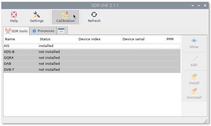
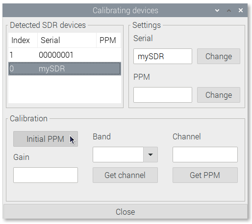
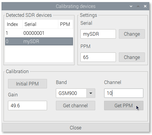
Click on Calibration
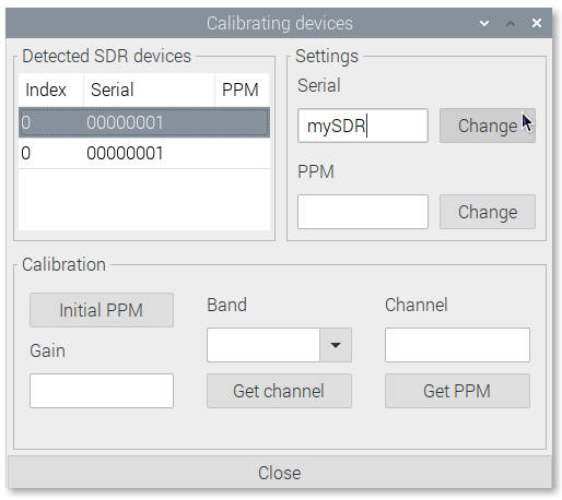
You will see the list of connected SDR devices. Select any of them, type a new name in Serial field and click on Change:
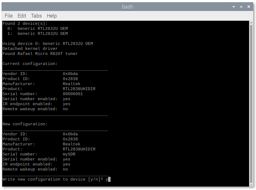
A new window will open asking for confirmation. Type y and press enter. Finally replug the device and open again SDR VHF to check the changes.
Calibrate devices
Every SDR device will have a small frequency error as it is cheaply mass produced and not tested for accuracy. This frequency error is linear across the spectrum, and can be adjusted in most SDR programs by entering a PPM (parts per million) offset value.
Important
- PPM values have a tolerance of +/-7
- PPM values can be negative
- If you do not find the correct PPM you will not get AIS data
- Some devices have a built-in temperature compensated oscillator (TCXO) that provides a PPM close to 0. These devices do not require calibration
If your device does not have TCXO, you need to know what its PPM value is, that is why we have added a tool to find it using GSM frequencies.
Before starting the calibration process, make sure there is an antenna connected to your device.
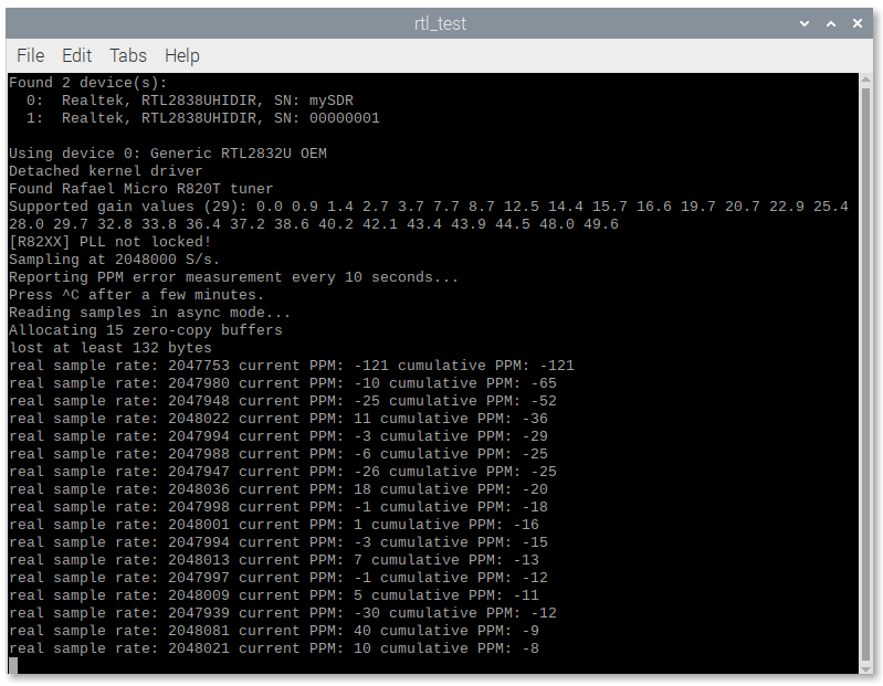
Go to Calibration again, select the device and click Initial PPM to get an approach to your PPM value:
The PPM value will change with temperature, so let the device run for at least 30 minutes. The longer you let the program calculate the better result you will get. If you run the program for hours you will get almost the final PPM but if you do not have time just wait for the value to stabilize.
Write down the stabilized PPM value and the maximum supported gain value for your device (usually 49.6).
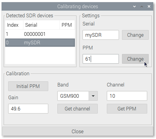
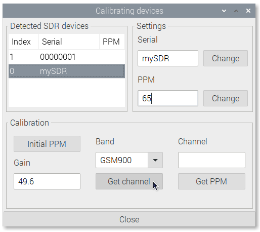
Close the program and put the PPM value in the PPM field and the maximum supported gain value in the Gain field.
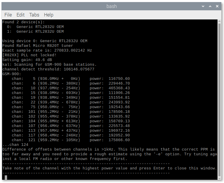
Select the GSM band for your zone and press Get channel:
Write down the channel with the highest power value and close the window:
Put the strongest channel into Channel field and press Get PPM:
Write down the final PPM value and close the window:
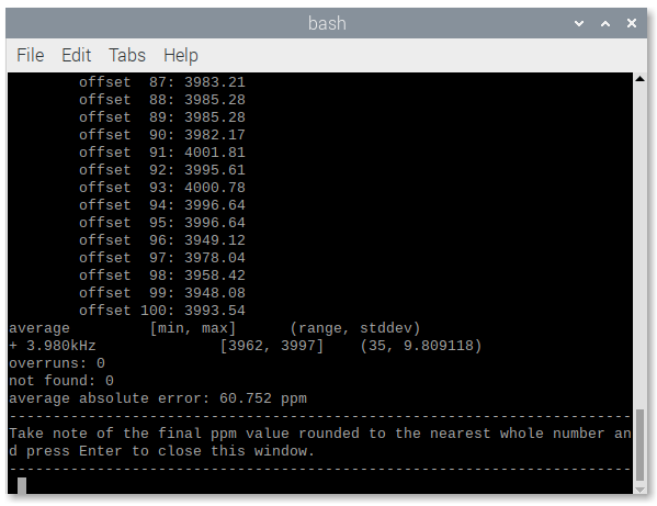
Put the final PPM into the PPM field without decimals rounding the value to the nearest integer number, click on Change and you are done: